NBD-OM-001 · section 3
Halls
The rooms where the computation happens: aisles, racks, cabling, air, fire, and the absence of light.
Revision 0 (draft01) · published 2026-09-29 04:03-07:00 · source ff3c1ff
3.1 Data hall layout
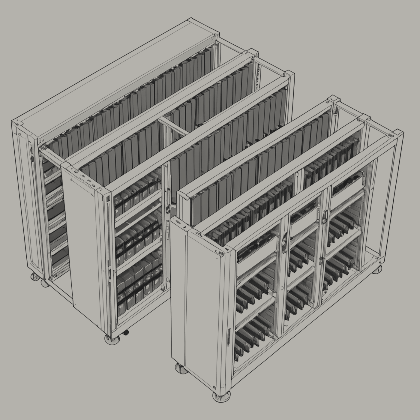
Each data hall is a long rectangular room holding rows of equipment racks. The rows are separated by aisles. Every aisle is either cold (air is supplied into it) or hot (air is exhausted from it), and the two alternate across the hall.
The air-cooled halls are identical. A drawing of one is a drawing of all of them. (The densest halls are cooled by immersion instead; Section 5.6.) See Fig. 3.1.
| Parameter | Value |
|---|---|
| Halls | Identical; count recorded in the site register |
| Layout | Alternating hot and cold aisles |
| Floor | Raised, on pedestals; services beneath |
| Ceiling | Cable trays and containment above the racks |
| Occupancy | None |
3.2 Aisle containment
Cold aisles are enclosed at their ends by doors and above by panels, so that the supplied air cannot mix with the exhaust. The doors are sliding and close automatically. They are opened by robotic equipment (Section 4) and by nothing else.
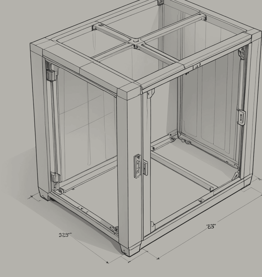
Holding a containment door open disturbs the airflow of the entire row. The facility closes any door left open.
3.3 Racks
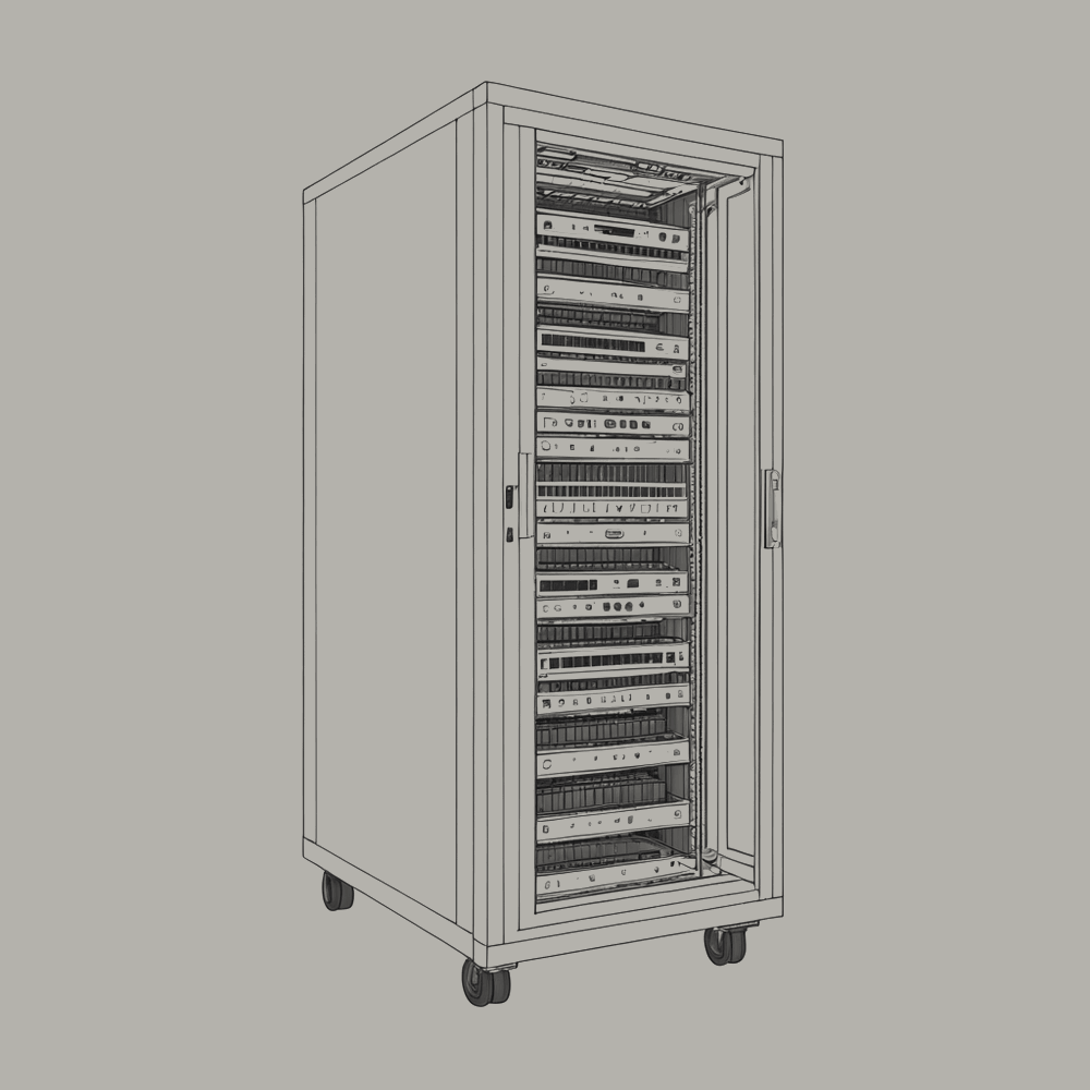
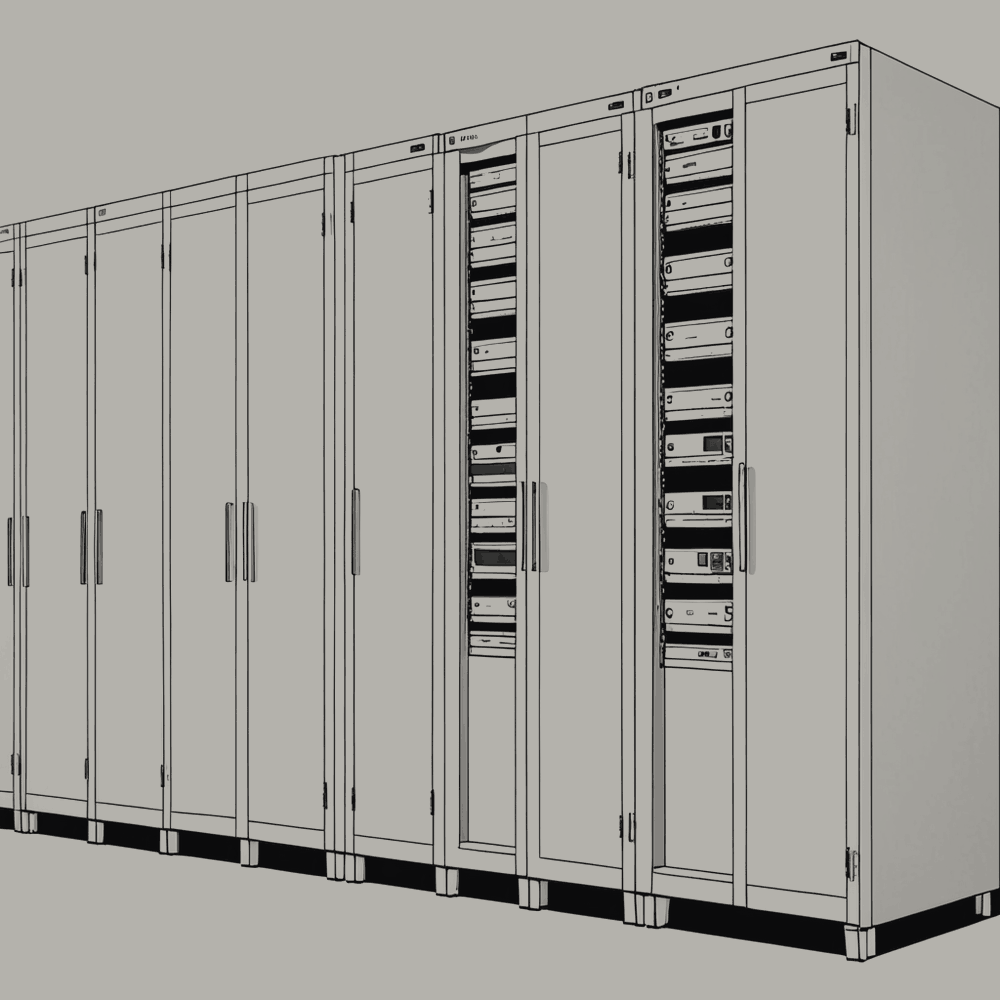
A rack is a steel frame of standard width and height into which equipment is mounted. Each rack in the facility is full. Each draws power from two independent supplies and connects to the network by fibre. See Fig. 3.3 and Fig. 3.4.
The rack is the unit in which the facility is planned and counted. When a rack fails, the facility does not repair it in place; it moves the work elsewhere and replaces what failed (Section 4.3).
3.4 Cabling and fibre
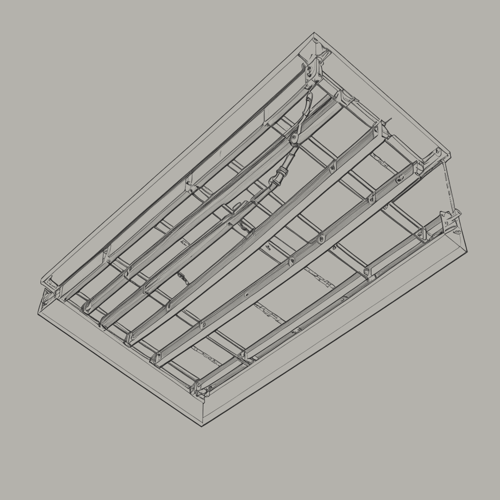
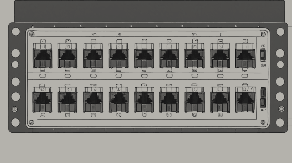
Power is distributed to the racks from overhead busways. Data travels between them by fibre, carried in trays above the racks and patched at distribution frames at the end of each row.
The quantity of fibre in a hall is large. Its length, laid end to end, is recorded in the site register. It is not repeated here because the number has no use to a reader.
3.5 Environmental conditions
| Condition | Setpoint | Note |
|---|---|---|
| Supply air temperature | Within the equipment's rated range | Set for the equipment, not for comfort |
| Humidity | Controlled | Prevents static discharge and condensation |
| Air changes | Continuous | — |
| Noise | Not controlled | No one is present to hear it |
| Lighting | 0 lux | See 3.7 |
3.6 Fire suppression
The halls are protected by an inert-gas (clean-agent) fire suppression system. On detection of a fire, the agent is released into the affected hall and the hall is sealed. The agent extinguishes the fire by removing what it needs to burn.
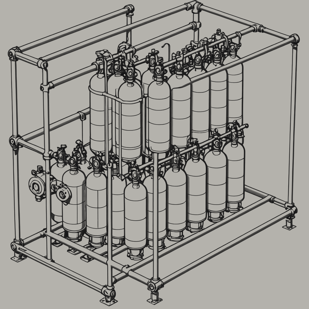
The suppression agent displaces breathable air. A person in a hall at the moment of discharge would be at risk. For this reason, discharge is inhibited while a person is detected (Procedure 2.5-1). For the same reason, a person should not be in a hall.
3.7 Lighting
The halls are lit to the level required by code. The lighting has been tested at commissioning and is tested periodically by the facility, which switches it on, confirms that it works, and switches it off.
Apart from those tests, and from the event described in Section 2.5, the halls are dark. The equipment does not need to see. Its status lights, which are small and blue and white, are the only light that normally falls in a hall, and they are not there to be seen either; they are a convention of equipment design, kept because nothing required that they be removed.
| performed by | verified by | date | signature |
|---|---|---|---|
Sign-off fields are provided for regulatory form. No entry is expected.