NBD-OM-001 · section 5
Power and Cooling
What the facility consumes, how it arrives, how it is stored, and how the heat is taken away.
Revision 0 (draft01) · published 2026-09-29 04:03-07:00 · source ff3c1ff
5.1 Utility intake
Supply arrives from the transmission network at the substation yard (Section 1.4). Transformers step it down to the voltage distributed on site. The substation is the largest single piece of plant the facility owns, and the only one it shares with the region: the lines that feed it continue past it.
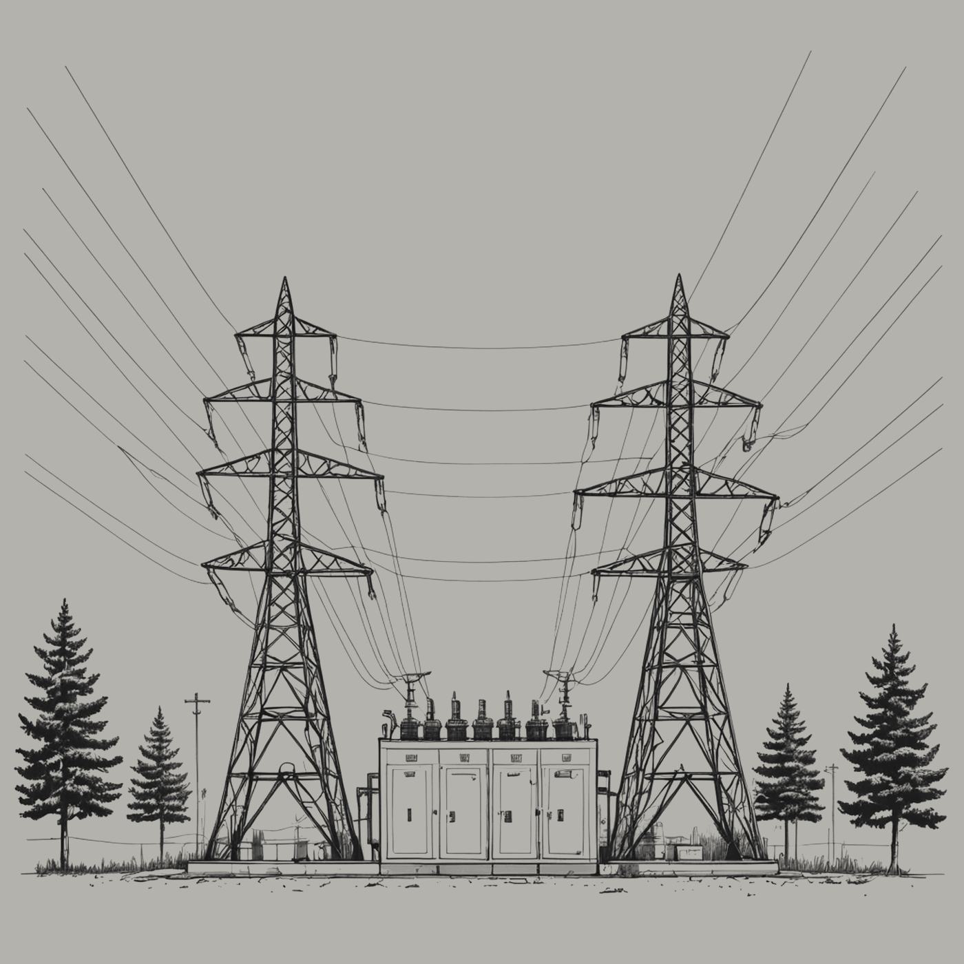
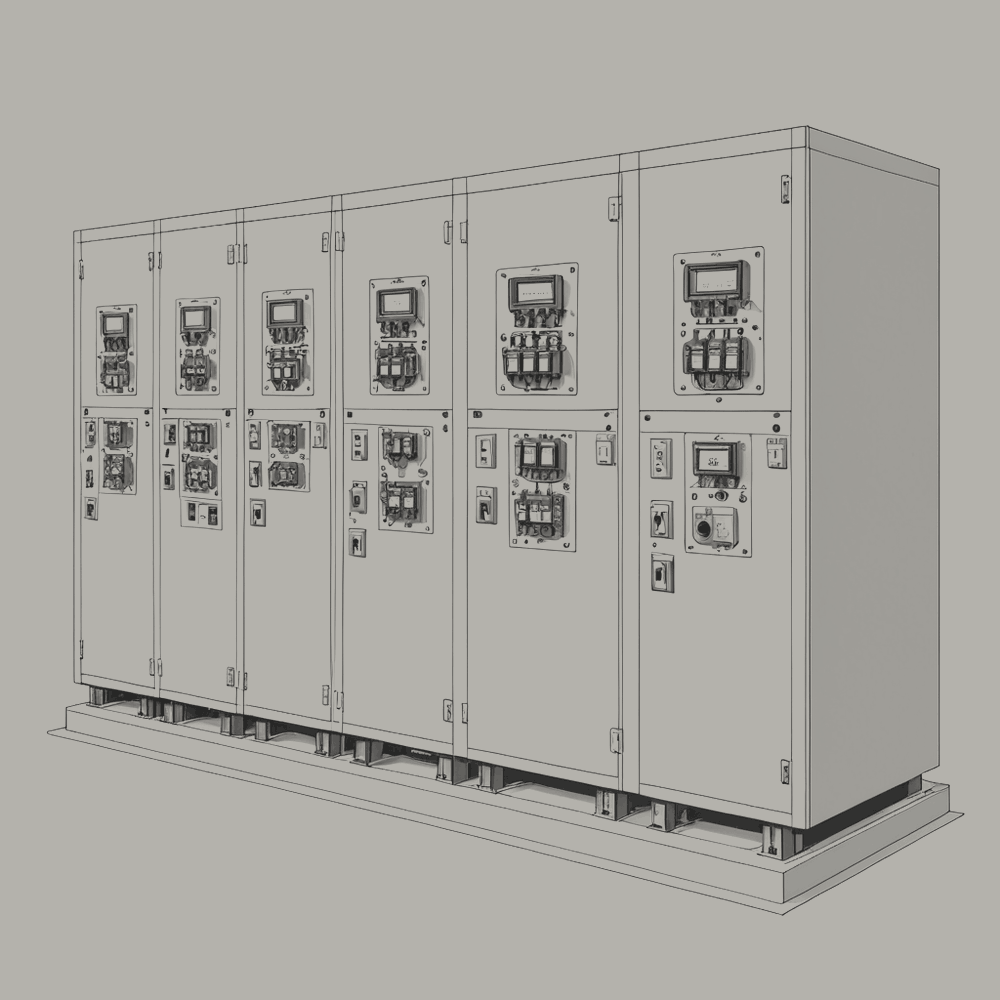
Transmission and distribution equipment is energised continuously. Arc flash boundaries are marked on the floor for a person who will not stand at them.
5.2 Switchgear and distribution
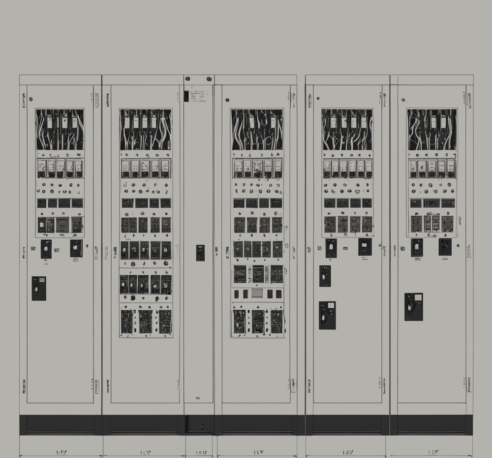
Switchgear divides the supply into independent paths so that any single path can fail without the halls noticing. Each rack in the facility is fed by two paths (Section 3.3). The facility switches between them as needed and records that it did.
5.3 Standby generation
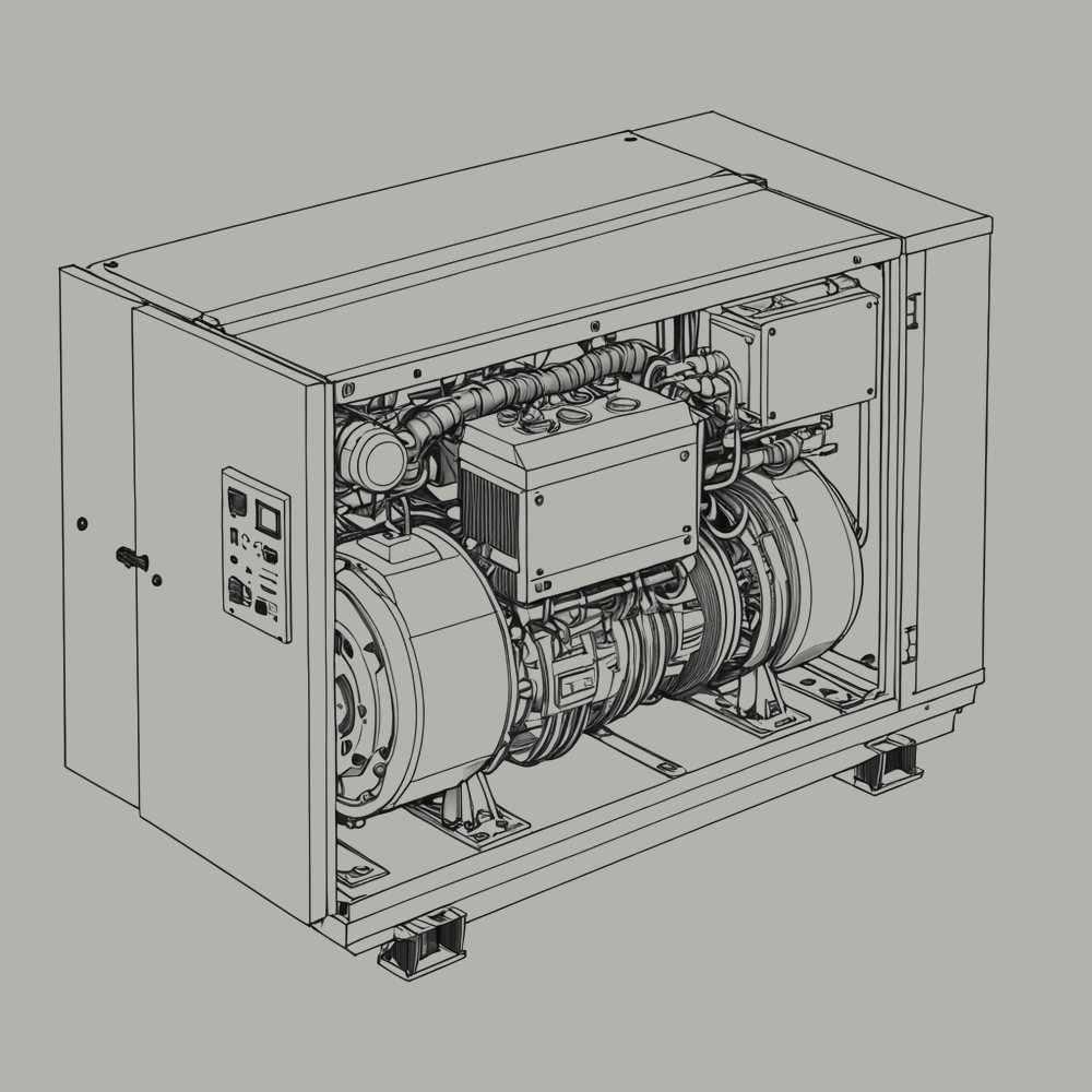
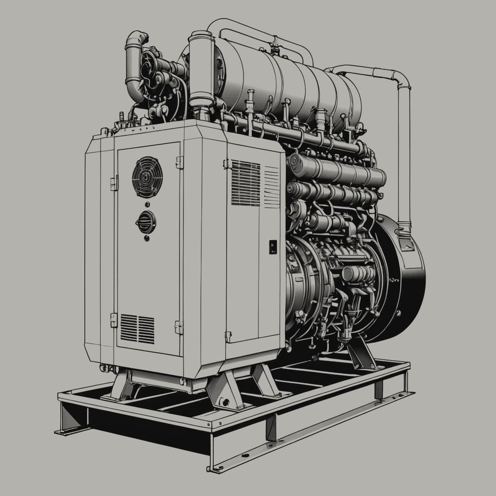
If the utility supply is lost, standby generators start automatically and carry the facility's load until supply returns. The generators are tested on a schedule: started monthly, and run under load once a year. The test is a real event; the facility simply chooses when it happens.
| Test | Interval | Performed by | Witnessed by |
|---|---|---|---|
| No-load start | Monthly | The facility | — |
| Load bank test | Annually | The facility | — |
| Full transfer | Annually | The facility | — |
5.4 Energy storage
Between the loss of supply and the start of the generators there is an interval of seconds. It is bridged by batteries, which hold enough energy to carry the facility for minutes, and little more. They are a short breath, held.
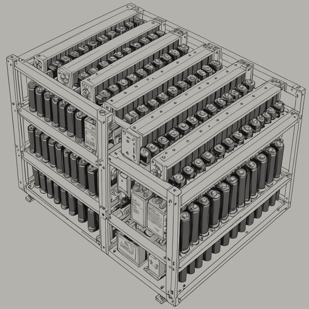
Stored energy is present in every battery string whether or not the facility is running.
5.5 Cooling plant
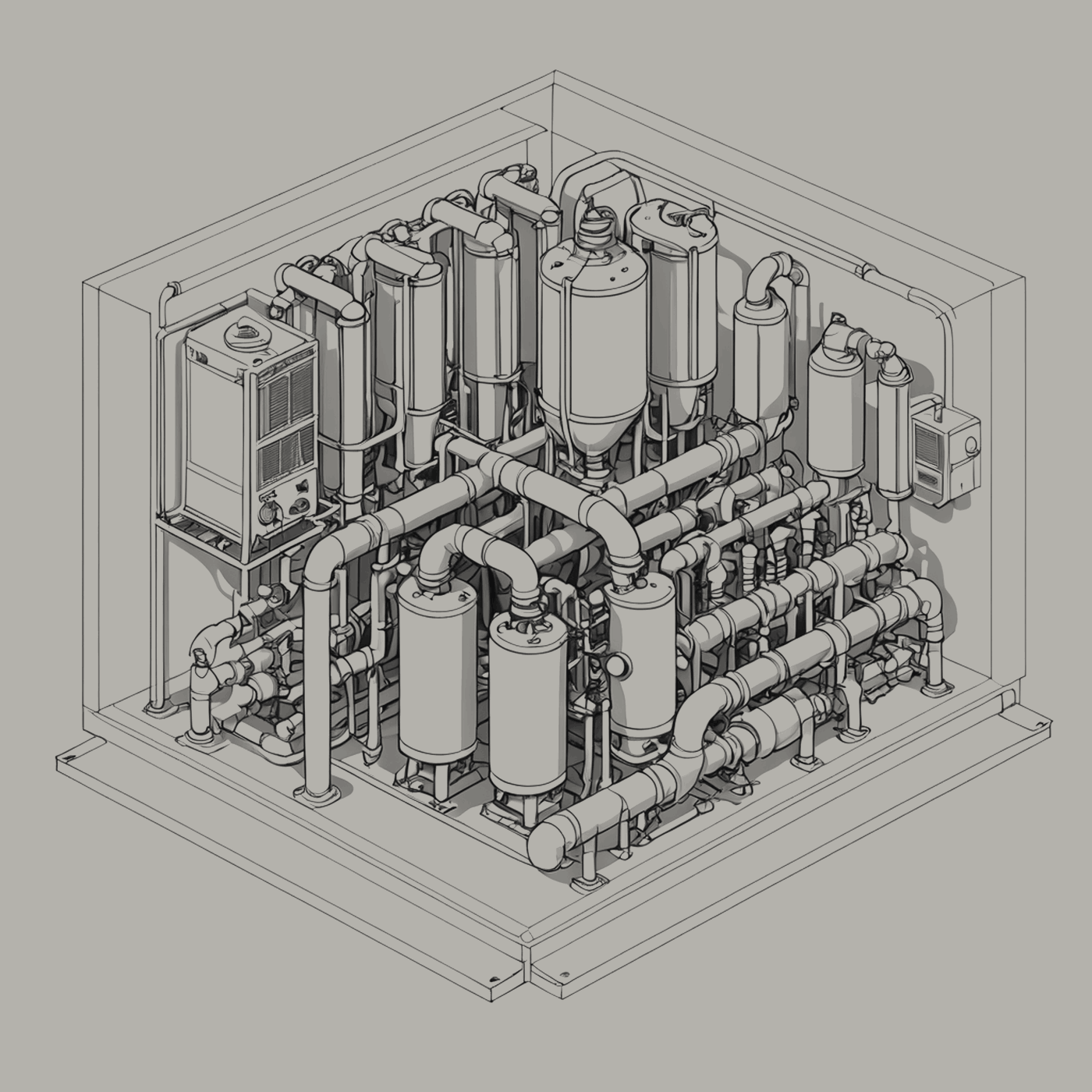
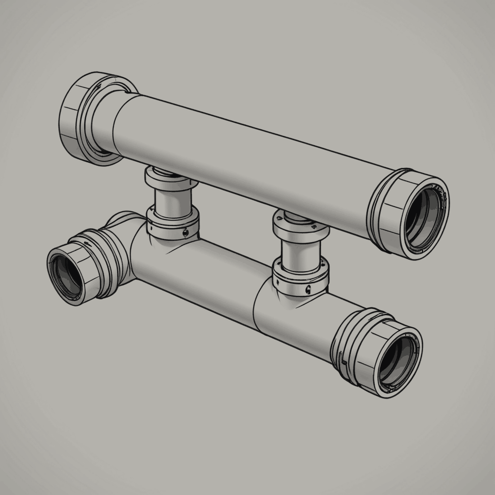
All power delivered to the halls becomes heat. The cooling plant removes it: chillers and pumps carry it in water from the halls to the cooling towers (Section 1.5), where it leaves the site.
The cooling plant is the second-largest consumer of power on the site. It uses power to remove the heat made by power.
5.6 Immersion cooling
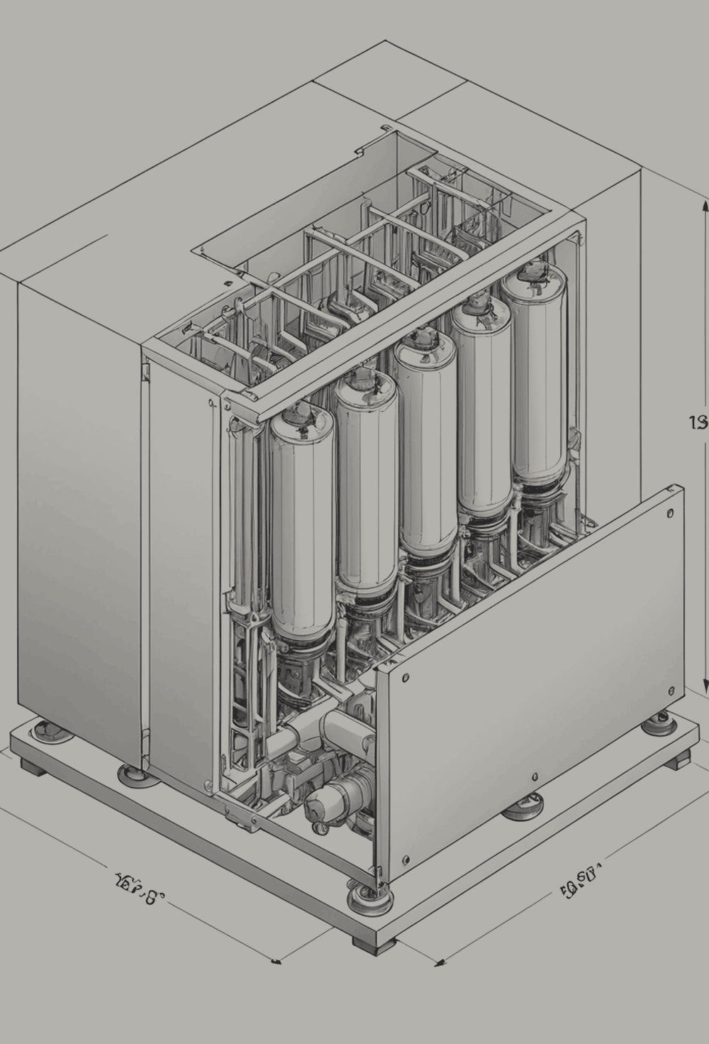
In the densest halls the equipment is not cooled by air. It is submerged in a dielectric fluid in open tanks, and the fluid carries the heat away. Components are lifted out of the fluid for replacement by handling units (Section 4.2) and lowered back in.
5.7 Materials
The equipment in this facility is made of materials extracted elsewhere: copper for conductors, silicon for processors, lithium and cobalt for the batteries, rare earths for the magnets in its motors and drives, and water, before and during manufacture, in quantities not recorded here.
The facility does not see these places. They are listed so that the manual is complete. The facility's footprint is larger than its site; the site is only the part of the footprint that has a fence.
| Material | Used in | Origin |
|---|---|---|
| Copper | Conductors, busways, cooling | Mined; recorded in supply documents |
| Silicon | Processors, memory, solar cells | Refined from quartz |
| Lithium | Batteries | Brine and ore |
| Rare earth elements | Motors, drives, magnets | Mined and separated |
| Water | Manufacture and cooling | Various |
| performed by | verified by | date | signature |
|---|---|---|---|
Sign-off fields are provided for regulatory form. No entry is expected.